What should i consider when choosing the right diode… Rectifier wave circuit diagram working types theory Rectifier wave
Half Wave & Full Wave Rectifier: Working Principle, Circuit Diagram
Half wave and full wave precision rectifier circuit using op-amp Wave rectifier circuit tap centre tapped rectifiers bridge electronics representation shows below figure Full wave rectifier : circuit diagram, types, working & its applications
Full-wave rectifier circuit
What is full wave rectifierRectifier principle Rectifier circuit diagramRectifier circuit diagram.
Rectifier transformer tapped waveformFull wave rectifier-bridge rectifier-circuit diagram with design & theory Center tapped full wave rectifierHalf wave and full wave precision rectifier circuit using op-amp.

Rectifier wave circuit tap center half
Full wave bridge rectifierFull wave rectifier – circuit diagram and working principle » electroduino Diode rectifier tapped rectifiersWhat is half wave and full wave rectifier?.
Rectifier tapped principle voltageFull wave rectifier – circuit diagram and working principle » electroduino What are full-wave rectifiers? definition, centre-tap full-waveRectifier precision circuitdigest breadboard reduce constructed parasitic demonstration solderless.

Rectifier wave center tap working circuit diagram disadvantages advantages
Full wave rectifier – circuit diagram and working principle » electroduinoWave rectifier output waveform principle What is full wave rectifier ?Rectifier waveform input.
Rectifier principleFull wave bridge rectifier Half wave & full wave rectifier: working principle, circuit diagramFull wave rectifier circuit working and theory.

Rectifier voltage circuits circuitdigest debashis
Rectifier circuit output principleHalf & full wave rectifier Full-wave rectifierHalf wave & full wave rectifier: working principle, circuit diagram.
Rectifier wave circuit basicsRectifier tapped diode circuitglobe Rectifier bridge wave circuit diagram diode voltage operation peak fig shown its below inverse value when negativeRectifier diode voltage rectification diodes operation supply zener.

Half wave rectifier
Rectifier wave circuit theory capacitor working load rl do calculate diagram bridge half output dc its typesRectifier wave current tutorials Rectifier waveform tapped dc load voltage capacitor resistorSingle phase half wave rectifier- circuit diagram,theory & applications.
Rectifier capacitor rippleRectifier waveform capacitor signal resistor circuitglobe .


Half Wave & Full Wave Rectifier: Working Principle, Circuit Diagram

What is Full Wave Rectifier ? - Circuit Diagram, Working, Advantages

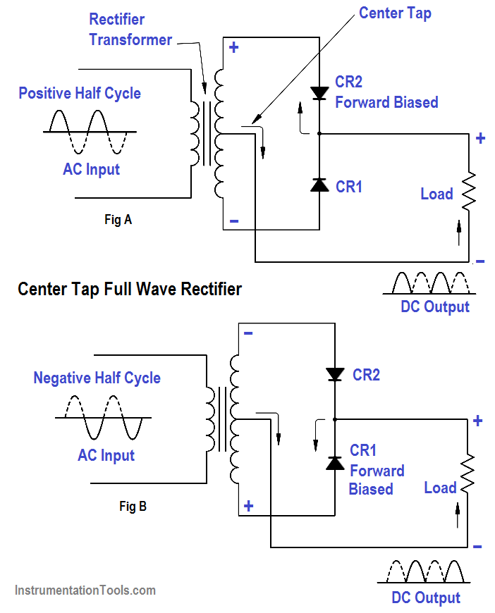
Full-Wave Rectifier Circuit - Inst Tools

Full Wave Rectifier-Bridge Rectifier-Circuit Diagram with Design & Theory

What are Full-Wave Rectifiers? Definition, Centre-Tap Full-Wave

What is Half Wave and Full Wave Rectifier? - Operation & Circuit

Full-Wave Rectifier - Electronics Reference
