Rectifier waveform Full wave rectifier with rl load and freewheeling diode Rectifier bridge diode wave circuit schematic using troubleshooting bit circuitlab created
Solved The sinusoidal signal source Eg(t) used to drive the | Chegg.com
Rectifier phase bridge single wave load diode rl Derivation rectifier voltage average wave bridge diode power 3phase electronics Rectifier bridge diodes wave make
Rectifier bridge wave 9v used diode zener ripple voltage regulated values load 200mv maximum sinusoidal signal drive source solved has
13+ bridge diode diagramFull wave bridge rectifier Rectifier diode voltage capacitor diodes disadvantages dac calculations volt circuits rectify gelijkrichterRectifier bridge wave operation half animation working input cycle current positive forward during gif diodes reverse biased d3 d4 d1.
Rectifier diode wave bridge diagram diodes circuit electrical current according d3 d1 forward figure whenRectifier diodes Diode rectifier diodesCircuit design.
How does a full wave bridge rectifier work to convert ac into dc, and
Why does the full wave rectifier have four diodes instead of just oneSolved the sinusoidal signal source eg(t) used to drive the Explain full wave bridge rectifier with diagramHow to make a bridge (full wave) rectifier with 4 diodes.
Rectifier wave bridge circuit diodes negative operation forward becomes its figure below biasedDiode bridge rectifier Full wave diode rectifierPower electronics.

Full wave diode rectifier
Rectifier diode wave load rl freewheelingSingle phase full wave diode bridge rectifier with rl load(हिन्दी Rectifier bridge diode capacitor circuit resistor voltage filter output load electrical4u dc gif operation filtering through regulated mathematical analysis regulatorRectifier circuit wave bridge diodes diode output form sparkfun ac signal waveforms negative positive middle.
Full wave bridge rectifier operationRectifier diode wave bridge diodes electrical4u diagram .


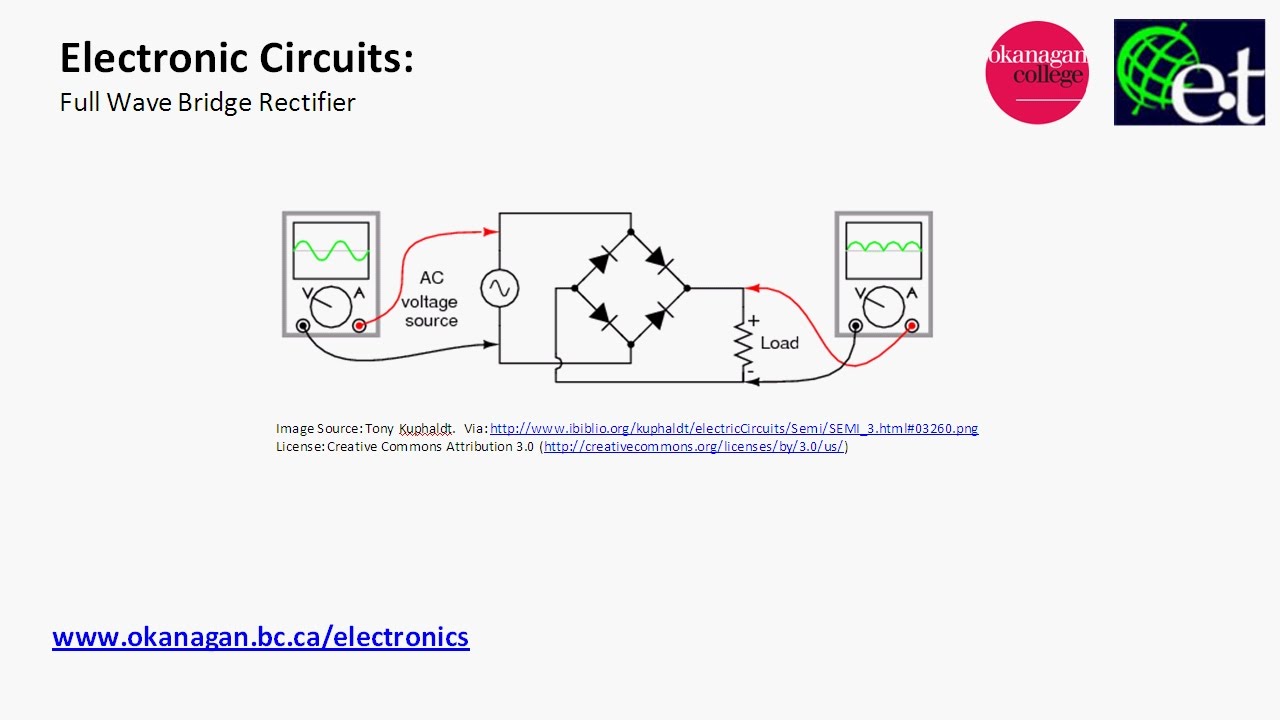
Full Wave Bridge Rectifier - its Operation, Advantages & Disadvantages

Full wave Rectifier with RL load and freewheeling diode - YouTube

Diode Bridge Rectifier | Electrical4U

Explain Full Wave Bridge Rectifier With Diagram - PCB Designs

Full Wave Bridge Rectifier Operation - Engineering Tutorial

Diodes - SparkFun Learn

Solved The sinusoidal signal source Eg(t) used to drive the | Chegg.com

power electronics - Average Voltage of a 3phase full wave bridge diode
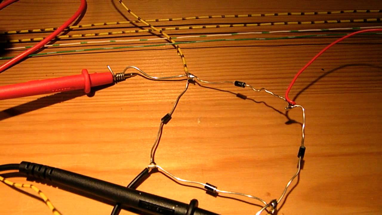
how to make a bridge (full wave) rectifier with 4 diodes - YouTube
